EC Indoor Blower Motors, Resistance is Futile
This motor is primarily applied to top tier multi-stage or modulating HVAC equipment. By 2005, approximate 15% of all new HVAC equipment was built with this motor. However, in 2006, there was a major shift in this segment driven by the 13 SEER regulation. At the same time this regulation was being developed, Regal Rexnord Corp. (“Regal Rexnord”)1 was developing a new type of ECM for indoor blower motor applications called “constant torque.” This technology would provide the same electrical efficiency as the constant airflow ECM but with fewer features and a lower cost.
The constant torque ECMs would be utilized by almost all HVAC OEM in the majority of their air handlers and package systems that moved from 10 SEER to 13 SEER in 2006. By the end of 2006 over 50% of new HVAC equipment was built with an ECM indoor blower motor. In 2019, another regulation focused on the electrical efficiency of fossil fuel appliances has again caused a major shift in this segment. Due to the Fan Energy Rating (FER) regulation that went into effect July 2019, the vast majority of furnaces that were still being built with PSC motors, are now built with constant torque ECMs.
So, it seems like now would be a good time for a refresher course on these two types of motors. Even though they are both built with ECM technology, they are very different in almost every aspect. This article will cover the basic design, input connections and airflow adjustment of each type of motor.
Constant airflow ECMs
Let’s start with the constant airflow (often referred to as “variable speed”) ECMs. I refer to these motors as “communicated ECMs.” The term “communicated” here refers to any type of communication between the HVACR system control and the motor control that meets the following criteria:
- The connections are fixed at both ends (typically with plug connections), meaning that they are not adjusted from one position to another to modify the operation of the ECM.
- Airflow adjustments related to the output of the motor are selected at the HVACR system control or user interface.
- The line-voltage inputs are separate from the communication inputs and are powered continuously from the HVAC system.
Figure 1 shows the type of plug connections used by Genteq® constant airflow ECMs.
The 5-pin plug is populated with the line voltage and ground inputs. The 16 and 4-pin plugs are used for communication. The 16-pin plug represents a communication style that was developed in the 1990s but is still used today. The 4-pin plug represents the latest communication style called digital serial communication (DSI) or simply “serial communication.”
When HVAC systems that use constant airflow ECMs are installed, there are numerous “setup” options related to all of the motors’ features and benefits. At a minimum, the factory default airflow settings should be checked to make sure that they match the capacity of the heating and/or cooling systems. However, most systems also allow for “fine tuning” of the heating and cooling airflow to maximize system performance and comfort. There are humidity control and continuous fan selections that can be tailored to the customer’s preferences as well. Because they can be directly related to various operational issues (or even component failures), these settings should always be checked—and adjusted, if needed—at the time of installation or commissioning. The installation manual should always be stored near the unit for future reference.
The two most common means for adjusting these settings are DIP switches or jumper pins located on the HVAC system control board. Both provide the same basic function. The position of the switch or jumper on the control board determines the selection of a particular feature or function and the output communication to the ECM.

Figure 1: Communicated ECMs
The HVAC system manufacturer provides charts (often labeled as “set-up” or “airflow” or “comfort” settings) that relate the position of each switch or jumper to its corresponding setting. In some cases, charts may be located on stickers on the HVAC unit itself, or they may be part of the schematic. Information may even be printed right on the control board, near the selections. The charts and complete instructions about each setting and how it affects the operation of the HVAC system are always found in the installation and/or service manual. Most HVAC system manufacturers create one manual for each model line they produce, and that manual contains all of the charts for every unit in that model line. There- fore, it is important to find the chart or charts that match the precise model number for the system on which you are working.
Please note the following:
- Many HVAC system control boards are manufactured with multiple sets of DIP switches or groups of jumper pins for the selection of additional features, such as time delays, thermostat choice, staging control, or built-in diagnostics. Some of these settings are not only imperative to the proper operation of the system, but also affect comfort and noise levels.
- Even though systems that utilize constant-airflow ECMs are predominantly multistage or modulating systems, there is typically one airflow selection that adjusts the heating or cooling airflow for all stages or operating points.
Figure 3 is an excerpt from the installation manual for a residential gas furnace.
Jumper pins typically are arranged in groups of columns or rows on the control board. Each group is labeled on the control board to identify its purpose. Each pin or pin set is labeled on the circuit board with a letter, word, abbreviation, or value.
The charts provided by the HVAC system manufacturer relate the position of the jumper in each group to a corresponding airflow value, comfort selection, or other feature (see Figure 4). The type of control board illustrated in this example from York® 2 requires the user to move a jumper or plug from one position to another (across two pins) to change selections.
Compared to jumper pins, DIP (dual in-line package) switches are smaller in size. Each switch is labeled with a number. The positions of the switch may be labeled as follows: on and off; or 1 and 0; or on with an arrow (see Figure 2 on pg. 23).
The switch numbers and position labels are very small. Depending on its orientation in the unit, the control board may appear upside down or sideways.
This can make it easy for a service technician to set a switch in the wrong position if he or she is not paying close attention. The charts provided by the HVAC system manufacturer relate the position of the switch to a corresponding airflow value, comfort selection, or other feature (see Figures 5 and 6).
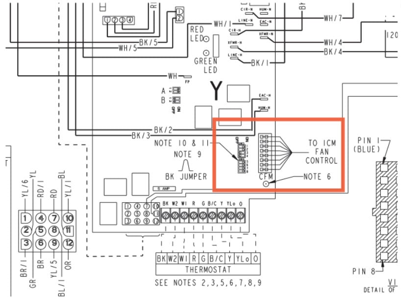
Figure 2: DIP switches (Trane® UY080R9V3W). Image courtesy of Trane®

Figure 3: Furnace control board schematic (York® TM9v)
Most fossil fuel heating systems have the heating airflow preset at the factory to operate with a temperature rise that is within a few degrees of the midpoint of the temperature rise range specified on the unit rating (data) plate. However, the technician should always measure the temperature rise and compare it to the information on the unit rating plate. There are several ways to modify the heating airflow if the temperature rise does not meet the specified range, or if adjustments are needed to improve airflow or register temperature.
The chart shown in Figure 5 (this time from Trane® 3) provides detailed temperature rise, airflow, and power values related to a pair of switch settings. Note that the factory default setting is identified as “Normal.” Also, notice that even though the values for first-stage and second-stage heat are given, there is only one selection that modifies the airflow for both stages.
| HIGH / LOW SPEED COOLING AND HEAT PUMP CFM | |||||
|---|---|---|---|---|---|
| 060B12 | 080B12 | Jumper Settings | |||
| High | Low | High | Low | COOL Tap | ADJ Tap* |
| 1343 | 865 | 1320 | 882 | A | B |
| 1116 | 727 | 1093 | 755 | B | B |
| 1235 | 791 | 1203 | 810 | A | A |
| 1026 | 661 | 1001 | 693 | B | A |
| 1079 | 709 | 1080 | 730 | A | C |
| 889 | 590 | 880 | 641 | C | B |
| 900 | 599 | 910 | 642 | B | C |
| 787 | 531 | 803 | 585 | D | B |
| 814 | 542 | 836 | 597 | C | A |
| 712 | 490 | 738 | 557 | D | A |
| 725 | 499 | 749 | 561 | C | C |
| 641 | 456 | 682 | 529 | D | C |
| HIGH / LOW HEAT CFM | |||||
| 060B12 | 080B12 | Jumper Settings | |||
| High | Low | High | Low | HEAT Tap | ADJ Tap* |
| 1364 | 843 | 1433 | 945 | A | Any |
| 1253 | 745 | 1320 | 887 | B | Any |
| 1102 | 660 | 1223 | 840 | C | Any |
| 1014 | 607 | 1134 | 768 | D | Any |
Figure 4: Airflow data (York® TM9V)
For most systems, the cooling air ow is also the heat pump heating air ow. Most units designed to be used in split systems are capable of operating with multiple sizes (capacities) of A/C or heat pump systems. Therefore, the factory default selection always must be checked and adjusted to match the installation.
Figure 6 shows an example of a chart from Trane that allows for the selection of cooling air ow by unit capacity (tonnage) and the ability to set the air ow at 350, 400, or 450 cfm per ton for more or less latent heat removal (dehumidification). In this example, four switches must be adjusted to achieve the proper selection.
These are just few examples of how different manufactures provide charts and functions for selecting air ow. Constant air ow driven systems also have many other options for selecting comfort features such as improved dehumidification and continuous fan. While many are similar, it’s important to be familiar with and follow the instructions provide for each individual HVAC system.
Many HVAC manufacturers also now offer communicating thermostats with on-screen menus. These menus may include some or all of the air ow and comfort selections previously discussed, as well as advanced diagnostic features and real-time operational values, such as cfm and TESP (total external static pressure). If the HVAC system control board utilizes DIP switches or jumper pins, their settings may be superseded by the communicating thermostat menu selections. Again, be sure to check the HVAC manufacturer’s literature for information related to these advanced thermostats.
| AIRFLOW SETTING | DIP SWITCH SETTING | EXTERNAL STATIC PRESSURE | |||||||
|---|---|---|---|---|---|---|---|---|---|
| SW 7 | SW 8 | 0.1 | 0.3 | 0.5 | 0.7 | 0.9 | |||
| HEATING 1ST STAGE |
Low | ON | ON | CFM TEMP. RISE WATTS |
800 56 105 |
800 56 140 |
800 56 180 |
800 56 220 |
800 56 265 |
| MEDIUM LOW | OFF | ON | CFM TEMP. RISE WATTS |
860 52 115 |
880 51 165 |
890 50 215 |
920 48 265 |
910 49 320 |
|
| NORMAL ** | ON | OFF | CFM TEMP. RISE WATTS |
960 46 150 |
990 45 200 |
1000 44 230 |
1020 44 310 |
1010 44 350 |
|
| HIGH | OFF | OFF | CFM TEMP. RISE WATTS | 1080 41 195 |
1110 40 255 |
1120 40 315 |
1120 40 365 |
1080 41 390 |
|
| HEATING 2ND STAGE |
LOW | ON | ON | CFM TEMP. RISE WATTS |
1100 62 205 |
1100 62 260 |
1120 61 320 |
1120 61 370 |
1090 63 400 |
| MEDIUM LOW | OFF | ON | CFM TEMP. RISE WATTS |
1210 57 265 |
1240 55 340 |
1260 54 410 |
1260 54 470 |
1130 61 430 |
|
| NORMAL ** | ON | OFF | CFM TEMP. RISE WATTS |
1360 50 365 |
1390 49 445 |
1400 49 500 |
1360 50 535 |
1210 57 475 |
|
| HIGH | OFF | OFF | CFM TEMP. RISE WATTS |
1360 50 355 |
1390 49 450 |
1400 49 520 |
1350 51 535 |
1180 58 465 |
|
| NOTES: * First letter may be “A” or “T” ** Factory setting |
1st Stage Capacity = 49,000 2nd Stage Capacity = 73,000 |
||||||||
Figure 5: Heating airflow (cfm) and power (watts) vs. external static pressure with filter for gas furnace (Trane UY080RV3W)
| OUTDOOR UNIT SIZE (TONS) |
AIRFLOW SETTING |
DIP SWITCH SETTING | EXTERNAL STATIC PRESSURE | ||||||||
| SW 1 | SW 2 | SW 3 | SW 4 | 0.1 | 0.3 | 0.5 | 0.7 | 0.9 | |||
| 2.0 | LOW (350 CFM/TON) |
ON | ON | OFF | ON | CFM WATTS |
750 84 |
750 122 |
750 154 |
720 185 |
710 221 |
| NORMAL (400 CFM/TON) |
ON | ON | OFF | OFF | CFM WATTS |
840 109 |
840 146 |
840 181 |
840 226 |
820 264 |
|
|
HIGH (450 CFM/TON) |
ON | ON | ON | OFF | CFM WATTS |
940 136 |
940 177 |
940 215 |
940 274 |
940 318 |
|
| 2.5 | LOW (350 CFM/TON) |
OFF | ON | OFF | ON | CFM WATTS |
850 113 |
850 150 |
870 200 |
890 250 |
890 295 |
| NORMAL (400 CFM/TON) |
OFF | ON | OFF | OFF | CFM WATTS |
960 150 |
990 200 |
1000 230 |
1020 305 |
1010 350 |
|
| HIGH (450 CFM/TON) |
OFF | ON | ON | OFF | CFM WATTS |
1080 195 |
1110 255 |
1120 315 |
1120 365 |
1080 390 |
|
| 3.0 | LOW (350 CFM/TON) |
ON | OFF | OFF | ON | CFM WATTS |
1020 175 |
1020 225 |
1040 280 |
1050 330 |
1050 375 |
| NORMAL (400 CFM/TON) |
ON | OFF | OFF | OFF | CFM WATTS |
1170 240 |
1180 300 |
1200 365 |
1200 415 |
1130 420 |
|
| HIGH (450 CFM/TON) |
ON | OFF | ON | OFF | CFM WATTS |
1290 310 |
1320 410 |
1350 470 |
1340 520 |
1150 440 |
|
| 3.5 | LOW (350 CFM/TON) |
OFF | OFF | OFF | ON | CFM WATTS |
1170 250 |
1190 315 |
1210 370 |
1210 435 |
1100 405 |
| NORMAL (400 CFM/TON) |
OFF | OFF | OFF | OFF | CFM WATTS |
1360 365 |
1390 445 |
1400 500 |
1360 535 |
1210 475 |
|
| HIGH (450 CFM/TON) |
OFF | OFF | ON | OFF | CFM WATTS |
1360 355 |
1390 450 |
1400 520 |
1350 535 |
1180 460 |
|
|
NOTES: * First letter may be “A” or “T”
|
|||||||||||
Figure 6: Cooling airflow (cfm) and power (watts) vs. external pressure with filter for gas furnace (Trane UY080RV3W)
Constant torque ECMs
Constant-torque ECMs are most commonly built using a multi-tap design similar to that of a PSC induction motor. Each tap (usually called a “speed tap”) is actually programmed with a torque value. The torque value for each tap is stored in the motor control. When the tap is energized, the motor control operates the motor at that value. This is also very similar to an induction motor in which the motor winding is tapped to create multiple speeds based on the torque created by each tap. However, that is where the similarities end. The Genteq® model Endura® Pro motor is an example of a multi-tap constant-torque ECM (see Figure 7).
The motor control is powered with continuous line voltage when the HVAC system’s disconnect is closed. The high-voltage terminals on the connection block of all Endura® Pro motor controls, regardless of the rated voltage, are labeled “L” (Line 1), “G” (ground), and “N” (neutral). The “N” terminal is connected to the neutral line on 15-V ac and 277-V ac systems, or to Line 2 on 208-/230-V ac and 460-V ac systems. Each model is built to operate at a single voltage source.
The five speed taps can be energized with 24 V ac or 15–33 V dc. By far the most commonly used input voltage is 24 V ac. The connection block is always labeled “C” for 24 V ac common and 1–5 for the speed taps. The ECM turns on and off when the speed taps are energized and de-energized (see Figure 7 on pg. 25).
To select the correct tap for heating and cooling airflow with constant-torque ECM- driven systems, follow the same criteria as those used with induction motor systems. The air- flow of any given tap is affected by the TESP (see Figure 9). Temperature rise on fossil fuel systems and airflow for cooling or heap pump systems should be measured to ensure accuracy. Always measure the TESP and verify that it is as close to the HVAC system manufacturer’s recommendation as possible. If the TESP is higher than recommended when the system is new and clean, it may be prone to nuisance failures and inadequate performance due to filter loading and/or the closing or blocking of registers and grilles by customers.
The schematic provided by the HVAC system manufacturer typically includes a leg- end that correlates the speed tap designation (lo, hi, heat, cool, fan, etc.) to the wire color, tap number, or both. There may also be a chart and/or notes related to suggested tap usage (see Figure 8).
The factory-selected heating tap speed (in fossil fuel systems) typically provides a temperature rise within a few degrees of the midpoint of the temperature rise range specified on the unit’s data plate at the recommended TESP (typically 0.5 in. w.c.). If the measured temperature rise at this speed does not fall within the required range, the TESP should be improved or a higher speed tap should be selected (if applicable). Before changing the factory-selected heating tap, always consult the airflow table in the installation manual and read all applicable notes related to adjusting the blower speed for heating mode operation.
The factory-selected cooling or heat pump tap speed is typically the highest speed (unless that is required for the heating tap). Most fossil fuel furnaces and air handlers are capable of operating with multiple sizes of connected A/C or heat pump systems.
The factory-selected cooling speed tap may need to be adjusted to match the installed system’s airflow requirement. Before changing the factory-selected cooling tap, always consult the airflow table in the installation manual. Such tables provide rated cfm values for each tap relative to the TESP (see Figure 9) and can be used to adjust airflow accurately for proper performance.
In this article, I referenced Genteq® motors as the examples for each ECM type. While there are other manufacturers of ECMs many use the same plug connections and methodology described here. If you follow the HVAC manufacturers literature related to a given type of ECM, the information provided here should serve as a good basis of understanding for all ECM driven systems.
Watch for Part 2 of this article series coming in the August 2020 issue of RSES Journal, where we will discuss the airflow performance characteristics of these motors related to Total External Static Pressure and their unique operating programs. In the third article (in the October 2020 issue of RSES Journal), we will discuss diagnostics and replacement.
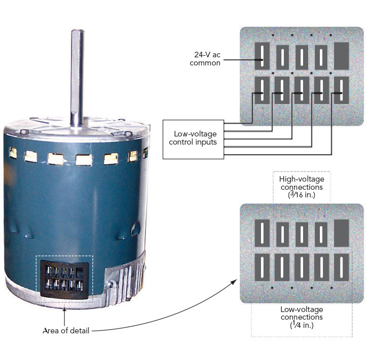
Figure 7: Electrical connection details

Figure 8: Example of wiring diagram (partial) for single-stage gas furnace
| FURNACE AIRFLOW (CFM) VS. STATIC PRESSURE (in.w.g.) | ||||||||||||||
| MODEL | SPEED TAP | 0.1 | 0.2 | 0.3 | 0.4 | 0.5 | 0.6 | 0.7 | 0.8 | 0.9 | ||||
| *UXIB060A9H31B | 4 - HIGH - Black 3 - MED-HIGH - Blue 2 - MED-LOW - Yellow 1 - LOW - Red |
1358 1196 1025 863 |
1327 1166 1000 830 |
1296 1135 975 797 |
1272 1109 943 762 |
1248 1082 910 726 |
1215 1053 878 687 |
1182 1023 845 648 |
1122 939 813 601 |
1061 955 780 554 |
||||
Figure 9: Example of airflow table (partial) for single-stage gas furnace
*“GE” is believed to be a trademark or trade name of the General Electric Co. 1 Regal Rexnord, Genteq® are trademarks or trade names of Regal Rexnord Corp. or one of its affiliated companies.
2 York is believed to be owned by Johnson Controls International plc or one of its affiliated companies. 3 Trane is a subsidiary of Trane Technologies.
Christopher Mohalley is the Training Manager for Regal Rexnord. He has applied his 25+ years of HVAC field experience, instruction and extensive product training to create a nationally-recognized ECM training program. He serves as a NATE Technical Committee SME, is a member of RSES and is NATE certified in all HVAC disciplines.
Interested in reading more about this topic? Check out Mohalley’s book Understanding Electronically Commutated Motors (SKU 200-523x), published as a part of the RSES Sustainability Series at www.rses.org/store. Use promo code ECM2020 and get 10% off the purchase price.
"EC Indoor Blower Motors, Resistance is Futile", by Christopher Mohalley. June 2020 feature reposted with permission from RSES Journal, www.rsesjournal.com.